Docklight software is my favourite engineering tools for any of my data communication projects. You can use this software to observe and control the exact data bytes sent and received.
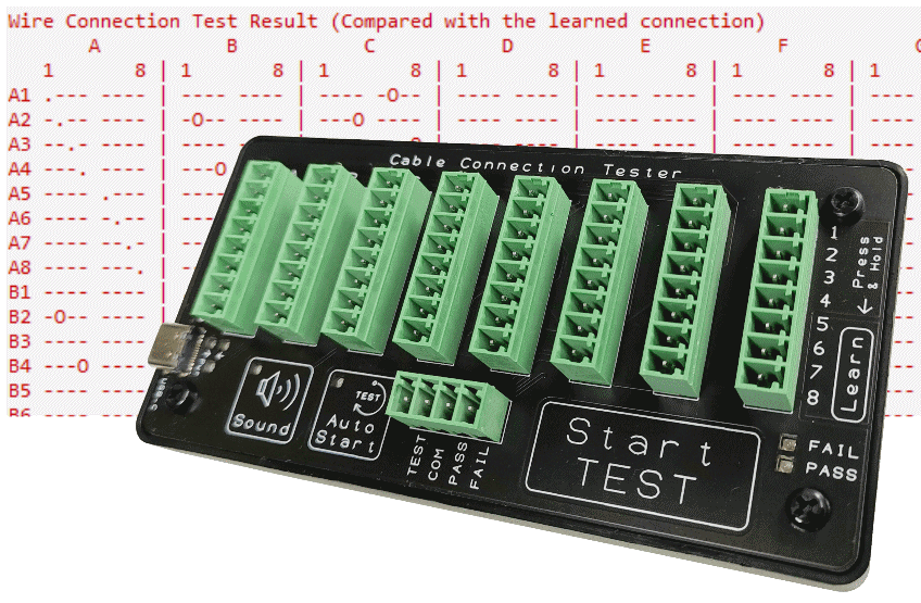
In this setup, I am going to show you how you can also use this Docklight tool as a software to generate the test result from the cable tester via the virtual serial COM port. It should also give you an insight how you can write you own software to read out the report and perform your own data interpretation from that report.
This setup guide assumes that you are using a Windows Operating System on your computer.
If you have further questions after going through this tutorial setup, feel free to email to us.
Download Docklight
You can click here to download
your free Docklight software (file size is about 5Mb),
or visit the official website for more information https://docklight.de/
Install Docklight to your computer.
Docklight User Step-By-Step Guide
Step 1: Connect up the Cable Tester
Connect up the cable tester to your Windows operating system via the USB cable.
Step 2: Check COM port number
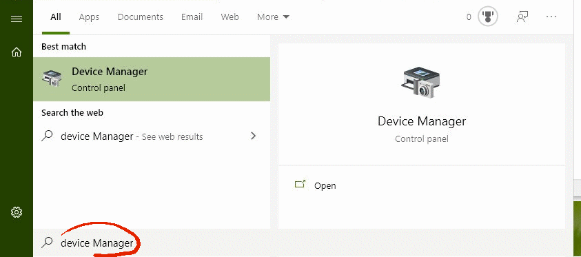
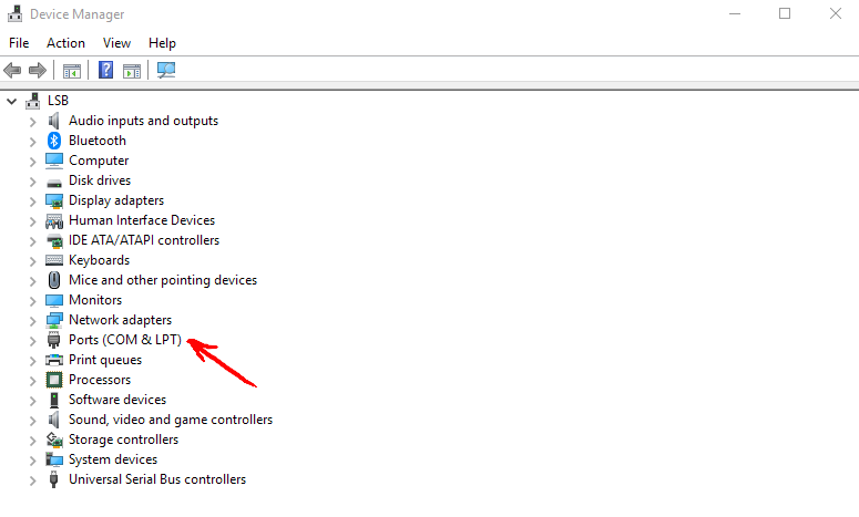
When you open up your Device Manager, you should come to this screen on your right.
Take note of the newly added device under the category Ports (COM & LPT). You should see the following line of text “USB Serial Port (COM6)“
In this example, the serial com port is COM6. It may appear a different COM port number on your system.
If there is multiple line of serial port devices, you can plug out and in the cable tester device to verify which COM port number belongs to the cable tester.
Step 3: Setup Docklight
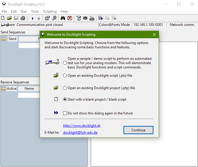
Open the Docklight software.
You can start by by selecting “Start with a blank project / blank script“, then click Continue.
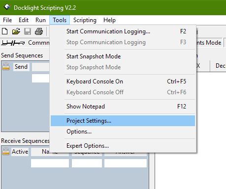
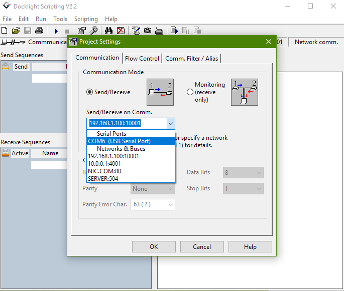
You should see this Project Settings menu pops up. Ensure that you are in the Communication tab.
On the drop down box, select the COM port number that you have with your cable tester.
In our example it is “COM6 (USB Serial Port)“
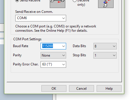
Select the Baud Rate to 115200.
Continue to ensure that the rest of the settings are the same as shown in the screenshot picture on this right side.
Speed: 115200bps
Data: 8 bits
Stop: 1 bit
Parity: None
Flow control: None
Click OK to complete and exit the settings dialog box.
Step 4: Operating and generating reports from the Cable Tester
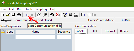
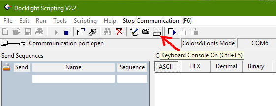
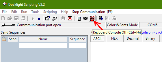
The Keyboard button icon should appear with a red color cross circle to indicate that the keyboard access has been enabled.
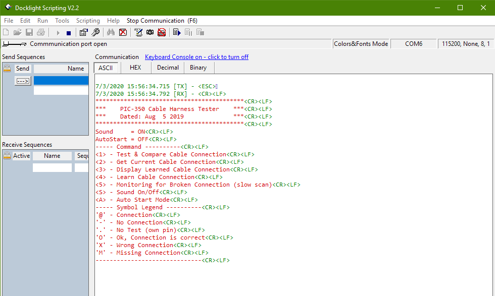
Ensure that the display tab selected is “ASCII“
Press ESC key to print out the user menu display.
This menu shows the keyboard command available from the cable tester device.
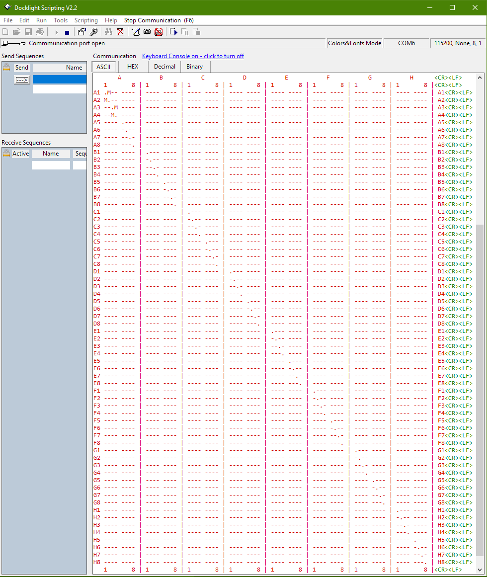
Press ‘1‘ to Test and Generate the test report.
You should see the test report as generated in a matrix table format.
Press ‘2‘ to map out the connected cable connection.
You can copy out this report for your own documentation.
We have a Google sheet template available for CCT-01 Cable Connection Tester user. You can also copy and and paste the report onto this spreadsheet. It can be use for your own documenation.
Click here for more information on this Google sheet for CCT-01 Cable Connection Tester.
That’s all. Enjoy playing with the cable tester.
You may like to check out the MobaXterm software for this cable tester.
