Introduction to MDB
MDB is a communication standard used in the vending machines industry to interlink numerous devices used in a vending system. It is one of the common standardised vending used around the world today. You can typically find this MDB connector connection in the following types of machines.
- Cold/Hot Drinks Vending Machines
- Toy Catchers Machines
- Coffee Dispenser Machines
- Packet Snacks Vending Machines
- Hot Food Baking Machines
Another vending standard is VCCS. It is adopted by the vending industry in Japan. Vending machine from Japan manufacturers typically uses VCCS instead of MDB interface standard.
MDB Connector details
Peripheral Connector
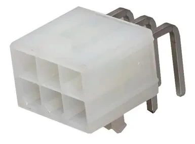
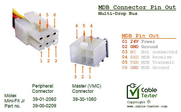
Molex Mini-Fit Jr 5569 Series, 6 ways (buy part number: 39-30-1060)
Available from Digikey part number: WM1353-ND
Master (VMC) Connector
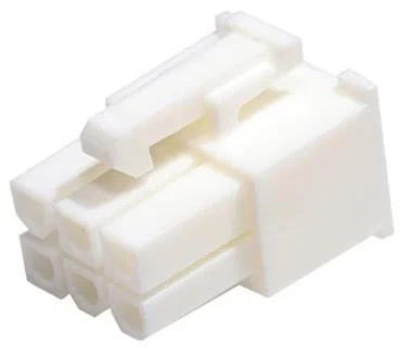
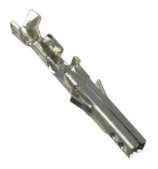
- Molex Mini-Fit Jr 5557 Series, 6 ways (part number: 39-01-2060)
– drawing (pdf 201MB),
– datasheet (pdf 32MB)
Available from Digikey part number: WM3702-ND - Molex Insert pins –
- for 28AWG to 22AWG (part number: 39-00-0209, 39-00-0210, 39-00-0215, 39-00-0216)
- for 24AWG to 18AWG (part number: 39-00-0207, 39-00-0208, 39-00-0213, 39-00-0214)
- for 16AWG (part number: 39-00-0211, 39-00-0212, 39-00-0217, 39-00-0218)
Available from Digikey: WM2823, ???, WM3697, WM19539,
WM3116, WM16519, WM3117, WM13483-ND,
WM14176, WM13482-ND, WM3118, WM13484-ND
Alternative connectors available
- ULTICOMP (MC34509)
- TE CONNECTIVITY (794954-6, 15)
Available from Digikey: A30592-ND
Tools Accessories
- MOLEX 11-03-0044 Extraction Tool for Mini-Fit Jr Crimp Terminals
Available from Digikey: WM9918-ND
MDB Communication Protocol Documentation
Also known as MDB ICP (Multi Drop Bus, Internal Communication Protocol). The following are the details containing the communication protocol standard used on the MDB connection interface.
Serial Communication Configuration:
9600bps NRZ, 1 Start Bit, 8 Data Bits, 1 Stop Bit, 1 Mode Bit, no hardware handshaking. 0-5V signal (TTL level).
The mode bit is a special 9th bit in the communication protocol, acting as an indicator to finish up an ongoing communication.
MDB Interface Circuit & Signal
The MDB interface is in a pull-up pull-down voltage and open-collector configuration. This allows the interface to other devices without being too much affected by the voltage system that the other devices are deployed with.
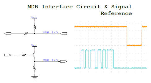
The signaling is pretty similar to the serial communication UART. You can implement MDB using the UART from the microcontroller. MDB protocol has a mode bit that uses the 9th bit of the UART serial protocol standard.
For data monitoring of this special serial data with a 9th bit, you can use Docklight serial terminal software to view. The software allows the configuration of the 9th bit. This allows you to monitor the MDB data communication. Not all the terminal software on the market allows configuration for the MDB communication protocol.
The VMC (or master device) controls the communication, to poll for slave response. Response from the slave device must be within a time frame of 5msec.

