I2C is a name short form for Inter-Integrated Circuit. I2C is a simple two-wire serial protocol used to communicate between chips in an embedded system on a PCB board. I2C communication consist of two signal lines SCL and SDA. SCL is used for clock synchronous and SDA is used for data.
I2C is not originally designed as a communication protocol over the cable. It is mean for communication between IC chips on a PCB board.
The convenience of I2C allows a modular function to be added to the circuit without affecting the overall design. This popular feature of using I2C led to people using it as a protocol to communicate between circuit board modules over a cable. This is usually 4 wires cable. Two wires (SDA, SCL) for the data. Two wires (VCC, GND) for the power. VCC is usually either 5V or 3.3V.
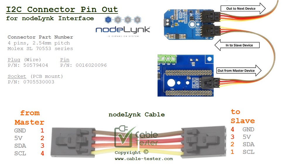
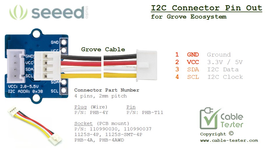
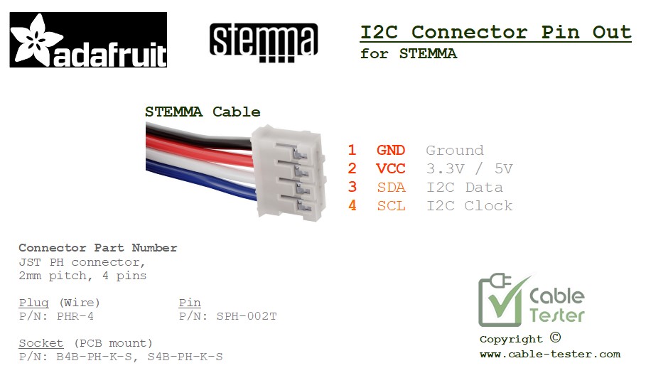
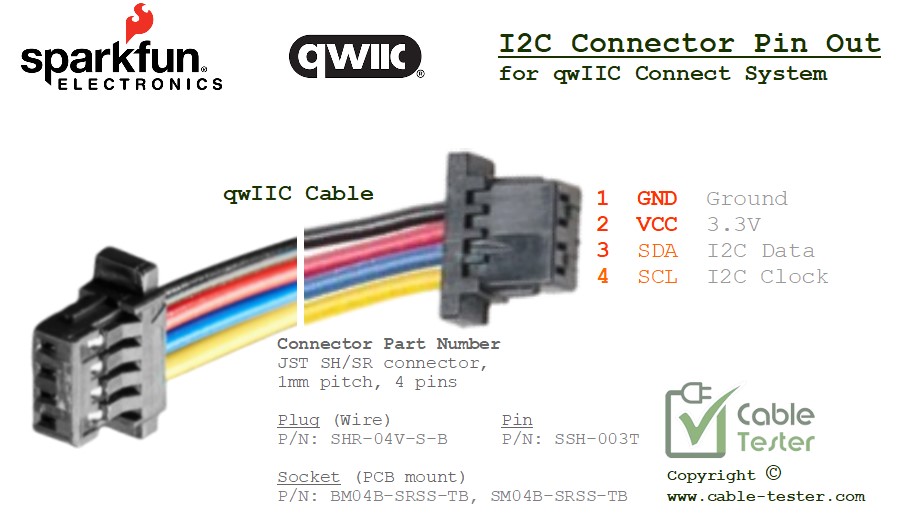
Electronic circuit module-producing companies coming up with their own I2C ecosystem standard. They are still the same basic I2C 4-wire cable. However, the type of connector used and the pin-out varies. This leads to some variation of the I2C cable system standard.
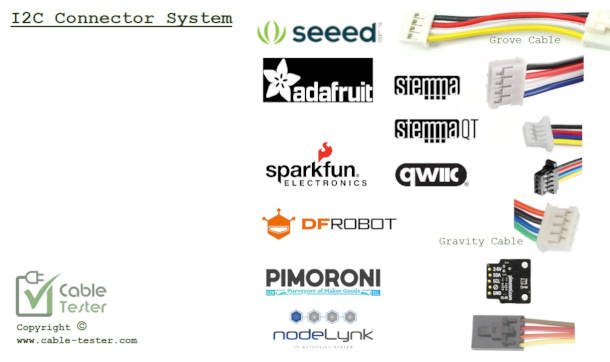
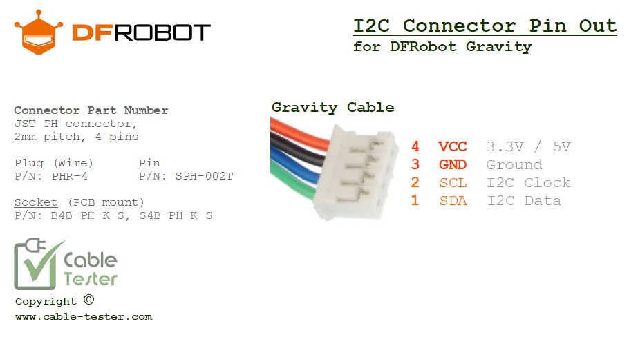
There is not yet an international standard for an I2C cabling system. The following presents the available I2C cable standard and pin out created by various system brands on the market.
At this moment of writing, there are 5 types of I2C cable systems that I have found, out of the seven I2C system brand names. Those with the same background colour mean that the cabling system is compatible and can be inter-swap with one another.
The recommended standard I2C cabling to implement, I would personally prefer to follow
- Grove (Seeed Studio), STEMMA (Adafruit) for standard I2C cabling system.
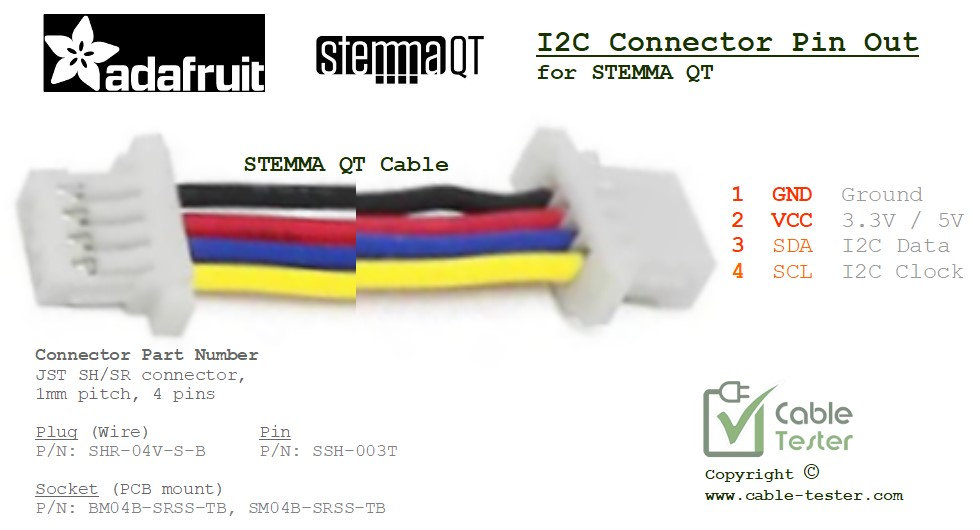
- qwIIC (Sparkfun), STEMMA QT (Adafruit) for mini-connector I2C cabling system.
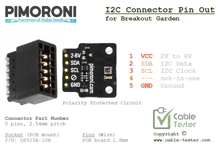
Breakout Garden (PIMORONI)
2.54mm pitch
nodeLynk Interface
2.54mm pitch
