Are you having a hard time figuring out the right plug connector for your printed circuit board (PCB) ?
How do you identify the socket connector on your PCB board?
There are too many connectors from on the market. Numerous brands and part numbers. Looking for the right connector can be very tedious. We need a way to reverse engineer the type of socket connector to help us find the mating plug.
There are big connectors and small pitch connectors. A wide range of connector products on the market. They are designed for various application which requires different wire size or current (power).
Before you start following this guide to identify your connector, search and check the documentation of your circuit board product to see if the specific connector is documented.
This is a step-by-step guide page to help you find the right plug to fit into the socket on your electronic circuit board.
- Step 1: Preparing the tools
- Step 2: Measure the pitch of the connector.
- Step 3: Match the standardised pitch.
- Step 4: Search from the connector list.
Step 1: Preparing the tools
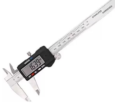
A precision tool like an vernier calliper is recommended for the measurement. It is going to help you correctly identify the pitch of the connector and narrow it down to the specific connector part number.
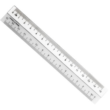
If you do not have a precision measurement tool on hand, a simple ruler and magnifying glass may do the job as well. Just that an incorrect measurement can mislead you towards the wrong connector mating plug.
- A vernier calliper (for precision measuring),
- or a simple ruler (if you do not have a calliper)
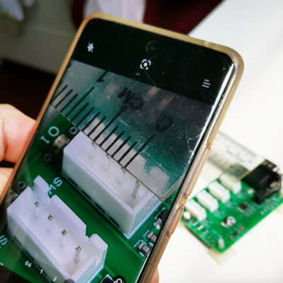
- a magnifying glass or phone camera if the connector is too small for your eyes.
Step 2: Measuring the pitch of the connector
This is the most important step in narrowing down the right plug for the socket on your PCB board.
Getting this step done right, it is already 80% of the job done. This is why a precision tool is recommended for the measurement. If you do not have a precision measurement tool on hand, a simple ruler and magnifying glass may do the job as well. Just that a wrong measurement may mislead you towards the wrong connector mating plug.
Measuring the pitch
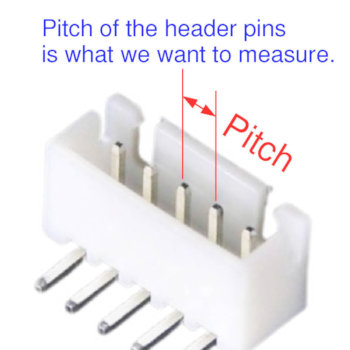
The pitch of the connector is the distance between the header pins of the connector. This can usually uniquely identify the connector to a list of connectors based on pitch size alone.
The pitch distance is from the centre pin to the centre pin of the adjacent pin on the header connector. While this is what defines the pitch, it is however difficult to measure from the center of the header pin in actual practice.
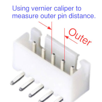
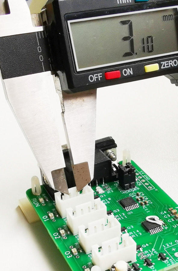
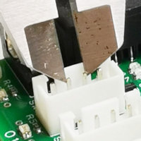
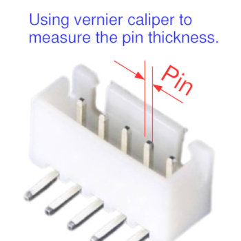
So instead of measuring from the center of the pin, we measure the outer side of the pin and subtract it by the pin thickness. This will give us an equivalent of the pitch size.
Measuring the outer pins
Measuring pin thickness
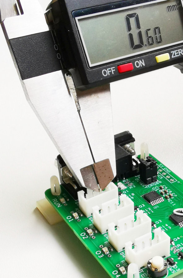
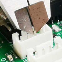
Calculate the pitch
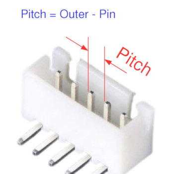
Computing the equivalent pitch size of this connector socket.
Pitch size = Outer distance – Pin thickness
Pitch size = 3.1mm – 0.6mm = 2.5mm
Pitch size = 2.5mm
This concludes that the pitch of this connector is 2.5mm.
Measurement without using a precision tool
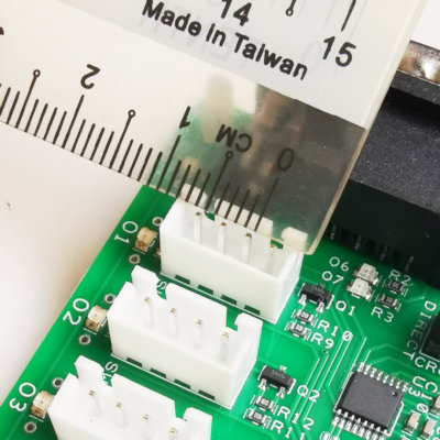
Instead of using a precision tool, you can also use a simple ruler to estimate the pitch of the connector. It is not precise in reading, not recommended, but it is better than no measurement.
You can use a magnifying glass or a camera phone to help you capture the measurement, and permit you to measure the pitch visually.
A tip to improve the accuracy when measuring using a simple ruler is to measure the outer side distance over more pins instead of just the adjacent pins. The more the better.
For example in this 4-pin connector example, measure the outer distance between pin 1 and pin 4. This will give you a reading close to 8.1mm. Subtract this by the pin thickness of 0.6mm and divide the result by 3. This will return a result closer to the actual pitch of the connector.
You can also visit this page for other illustration of measuring the pitch of your connector header.
Step 3: Match the standardised pitch
Now that we know the pitch size of the connector, we need to determine the connector family next.
While there are many connector sizes on the market, the pitch sizes are consolidated into a few pitch sizes. The industry somehow practises a list of standard pitch distances.
The common pitch size that is available on the market:
- 0.3mm
- 0.5mm
- 0.8mm
- 1mm
- 1.27mm
- 1.5mm
- 2.0mm
- 2.5mm
- 2.54mm
- 3.5mm
- 3.81mm
- 3.96mm
- 4.2mm
- 5.0mm
- 5.08mm
- 6.3mm
Knowing this pitch size is important because it can help us to determine the pitch size especially when we are measuring using a less precision tool (simple ruler).
Using a simple ruler, your measured pitch result is 2.7mm. You can probably tell that 2.7mm is not a typical connector pitch size. Base on this pitch size list, the nearest pitch size to 2.7mm is 2.54mm. So a good estimate to this connector pitch would be both 2.54mm and 2.5mm.
Through this process, we can classify this connector to be of pitch 2.5mm or 2.54mm
Step 3: Search from the connector list
Now that the pitch family is identified, we can narrow down the search by narrowing the search to connectors with pitch of 2.5mm and 2.54mm.
The other identifier is the number of pins on the connector. Count the number of pins. In our example it is 4 pins.
Next is to click into the 2.5mm/2.54mm pitch family of connectors and visually search for the parts.
Click here for the list of connectors that are grouped based on the pitch sizes.
- 1mm
- 1.5mm
- 2.0mm
- 2.54mm
- 3.81mm
- 5.0mm
- 5.08mm
Click here to go back to the wire-to-board connector list.
Click here to go back to the wire-to-board connector list.
